Imagine you are working on a design for a high efficiency windmill. Due to its complexities you need various custom parts, so you send out manufacturing drawings to various vendors for them to be made. Several weeks later you receive all the parts, but some do not fit.
One of your special shafts that should be 7/8 in. in diameter does not fit in its mating bearing. What happened? All the manufacturers were reputable and dealt with precision components, often used in aerospace applications. So, you grab your Vernier caliper and measure the section of the shaft only to discover that it has a diameter greater than what you requested, but by only 0.004 in. Yes, four thousandths of an inch can make a difference.
Any interference, defined here as the diameter of a hole that is smaller than the diameter of a shaft, will prevent parts from sliding together. They might have to be pressed on. If too large of an interference exists, it will degrade system performance, especially in bearings.
You specified the diameter of the shaft as 0.875 in., but the machine shop made the part to a 0.879 in. diameter. Why the difference? Some machine shops will apply a standard tolerance of 3 decimal places (±0.005) to un-toleranced dimensions, especially if they do not know the design intent.
Now, you’ve lost weeks of time while you wait for reworked parts.
Such a scenario can be avoided. While many machine shops use due diligence to verify non-toleranced dimensions, it is critical to understand the importance of tolerances, and how to use them correctly. Since parts need to be made either from larger pieces of material or built up from a powder or liquid, there’s no guarantee they will be exactly the size you want.

Fig 1. “Tolerance stack” will affect a part. Although every length dimension has the same tolerance, the tolerance between surfaces B and D can be as large as ±0.15 ( 1(b)) or as low as ±0.05 ( 1(c)), depending on the placement of the dimensions. It is up to you to decide which lengths are critical to the part’s function.
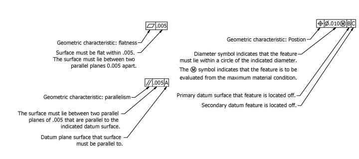
ASME Y14.5M defines tolerance as “the total amount a specific dimension is permitted to vary.” Tolerance is the difference between the maximum and minimum limits. This can be shown as upper and lower limits or an allowable amount above and below a nominal dimension. Either of these methods define the same range of allowable dimensions. In this example, a finished part is acceptable when its dimension is anywhere between 0.2498 and 0.2500 in.; outside of this range, it is rejected.
This range of allowable dimensions is the tolerance band. The larger the difference between the upper and lower limits, the larger the tolerance band, also considered a “looser” tolerance. Conversely, the smaller the difference, the smaller the tolerance band, also considered a “tighter” tolerance. Tolerances should always be used. Always. Ambiguity is not your friend. If you leave a dimension without a tolerance, no one else will know the importance, or the unimportance, of that dimension.
Benefits
When used correctly, you have much to gain when using tolerances. Parts with proper tolerances will fit as desired, be it a sliding fit, or a press fit.
It can also reduce costs. With unnecessarily tight tolerances, parts become more expensive to produce; there is no reason to apply a ±0.0002 tolerance when ±0.002 will do. Also, while some manufacturers apply their own set of standard tolerances to non–toleranced dimensions, many will not begin making parts until all features are defined, consuming valuable time and possibly pushing out delivery time.
Expecting parts to be made to the machinist’s best effort is not acceptable. The machinist does not know how parts interact, nor is he or she responsible for knowing. Furthermore, one machinist’s “best effort” may be maintaining the feature to within a few ten thousandths to the dimension indicated, whereas another may make the feature 0.015 in. larger or smaller than indicated.
Tolerances should not be used with hesitation. Just because a larger tolerance band is used, it doesn’t mean that parts will be sloppily made. In fact, depending on the manufacturer’s standards, shipped parts might have even tighter tolerances than you’ve specified. One good example is a bore in a gear. The specification might be ?0.250 +0.000−0.002, but the manufacturer may manufacture the bore to a tighter tolerance of ?0.2500 +0.0000−0.0005 simply because it is the standard to the particular manufacturer and this tighter tolerance is critical to the gear cutting process.
Additionally, by using proper tolerances, the liability of making the part correctly goes to the manufacturer. If the part is within tolerance and it doesn’t fit, the manufacturer cannot be held accountable. Dimensions without tolerances, however, leave the acceptable limits open. The manufacturer is not responsible for the design intent of the parts being made, and therefore cannot determine what an acceptable tolerance should be.
Proper application of tolerances
While tolerances are important, it is just as important to apply them correctly. One of the most important considerations when applying tolerances is fit. This is how shafts will fit into bearings or bushings, motors into pilot holes, and so on. Depending on your application, you might want a clearance fit to allow for expansion due to heat, a sliding fit for better positioning, or an interference (press) fit for holding capability. Information on limits and fits (among a plethora of information) can be found in the 28th edition of “Machinery’s Handbook” (ISBN 0831128003) for both U.S. Customary units and standard ISO fits.
Another consideration is how “tolerance stack” will affect the part. Suppose you have a shaft with four sections, each of different diameters, as shown in Figure 1. Although every length dimension has the same tolerance, the tolerance between surfaces B and D can be as large as ±0.15 in 1(b) or as low as ±0.05 in 1(c), depending on the placement of the dimensions. It is up to you to decide which lengths are critical to the part’s function.
Be careful when applying tolerances to radius or diameter dimensions. A tolerance on a radius will be doubled when measured as a diameter. A tolerance on a radius might be looser than intended, while one on a diameter might be tighter than intended. This effect is illustrated in figure 2(a) and 2(b). If 2(a) is used to manufacture the part, a hole diameter of 0.502 is acceptable.

Fig 2. A tolerance on a radius will be doubled when measured as a diameter. A tolerance on a radius might be looser than intended, while one on a diameter might be tighter than intended. If 2(a) is used to manufacture the part, a hole diameter of 0.502 is acceptable.
Also, you do not need to assume measurements will be rounded when determining if a part conforms to the specified tolerance. If a part is measured to be 0.2502 using a dial micrometer or other device, and the part’s dimension is supposed to be 0, the dimension is not rounded down to three decimal places, it is considered a nonconformance. ASME Y14.5M states dimensions “are used as if they were continued with zeros,” even if not shown.
You should also take into account any plating or finishing processes the part requires. A note should indicate if dimensions apply before or after them.
When using either MIN or MAX limits, ensure that if the dimension approaches infinity (in the case of MIN) or is zero (in the case of MAX), it does not hinder the design of the part. In figure 3(a) a MIN tolerance is used, possibly to ensure that there is a radius for reduction of stress concentration. However, figure 3(b) shows a dimension that is within tolerance, but may hinder the part’s function. Other features should clearly define the unstated limit.

Fig 3. With MIN or MAX limits, ensure that if the dimension approaches infinity (in the case of MIN) or is zero (in the case of MAX), it does not hinder the design of the part. A MIN tolerance can ensure that there is a radius for reduction of stress concentration. However, you can receive a part with a dimension that is within tolerance, but that may hinder the part’s function.
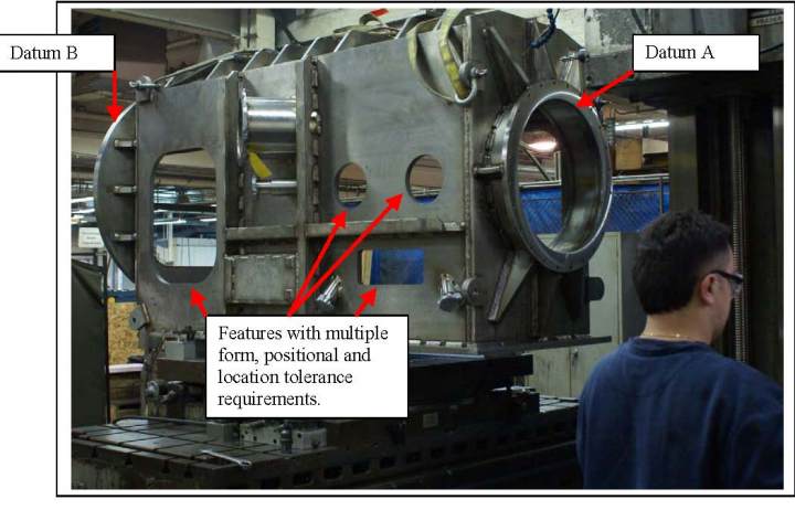
Both the location and size of alignment holes (such as for dowel pins) should not carry the same tolerances as clearance holes (such as for screws to go through). A certain deviation from nominal in the location of a dowel pinhole may cause your assembly to be impossible to assemble, while the same deviation in the location of clearance holes will likely cause no effect to the entire piece, except for perhaps a near-imperceptible aesthetic oddity.
While thoroughly dimensioning parts is important, take care to avoid redundancies. They may cause conflicts in inspection because certain features will be defined more than once in more than one method. If a dimension that will over define the part is desired, a reference dimension should be used, between parentheses and usually without tolerances, like dimension (M) in Figure 1(b). This dimension is derived from others or is repeated, usually in a different view.
Dimensional tolerances are key in getting parts you want. Using them appropriately will save time spent coordinating with the manufacturer, circumvent design issues, and reduce unnecessary costs.